

Le Tonkinois Varnish
B & D Murkin
UK main importers for
Le Tonkinois varnish
Flexidisc sander
Charger Repair 6 - Update 2014

Transformer removed from case.
Faulty transformer means this charger is beyond economic repair.
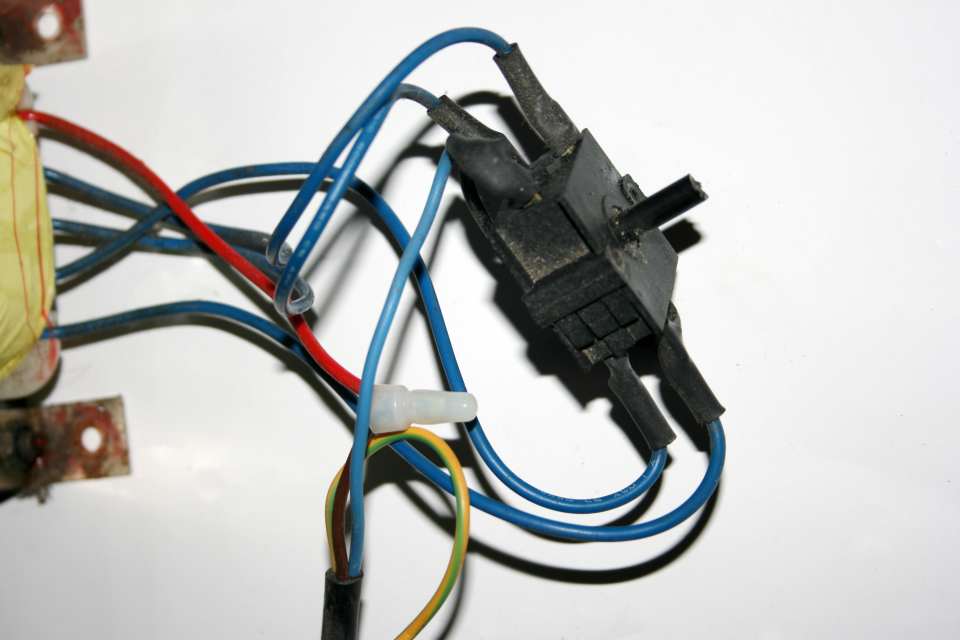
Charging switch.
Mains input wiring right, top to bottom.
240v Live
3
4
2
1
Charging switch wiring connections.
Wires are soldered to the terminals.
Transformer and charging switch circuit diagram.
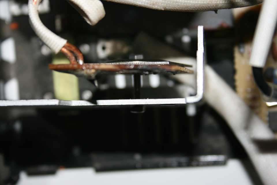
The diodes are clamped between a printed circuit board and a metal plate.
Diode replacement
Do not remove the diodes unless they are faulty, oxidation might cause bad contacts when re-

The fixing bolt was sealed with red threadlock.
I tried applying some heat but did not want to damage the diodes.

The four MIC RA501 diodes. These are 50 volt 50 amp devices. Yellow side goes to metal plate, black side to printed circuit. Thanks to Georges Pradon who found AMP 1502 50A alternatives on ebay April 2015. These are rated 200v and after also replacing the Mosfets his repair was successful.
Nut ground off with an angle grinder, part of the locking washer is still held in place by the threadlock. One diode has moved out of its circular recess into view.
Printed circuit board makes direct contact with the diodes. The board was so stiff to move it was unmanageable. Solution was to unsolder one set of the transformer wires. The circular protrusions visible on the metal plate mirror the recesses for the diodes on the other side.
Domed washer and flat plate fit on the non circuit side of the printed circuit board and apply pressure evenly.
Ground off bolt and locking washer on left. Replacement M3 20mm bolt was deliberately chosen to be longer than the original undamaged bolt and with a hex head instead of the Pozidrive head.
Charger stood on end for replacing the diodes. Three of the recesses are just visible. Access for tightening the nut is not good but ok. I photographed it on the floor but it was easier to work on a table.
The diodes have to be fitted with their yellow sides located in the recesses, then the bolt inserted through the washer, plate pcb and hole in the metal plate and tightened without moving them out of place. This is difficult. I found it easier to fit the bolt loosely as shown before pushing the diodes into position. Then I clamped the bolt head with a pair of forceps to stop it turning and applied downwards pressure to the top plate while tightening from underneath. It took a few tries to accomplish. Finally I added a star washer and second nut to lock the bolt before soldering the transformer connection back into the pcb.
I was concerned that oxidation on the contact surfaces would prevent good electrical contact but it seemed to be ok.
View of the pcb with the transformer removed.
Normal Charging Errors
There are 3 switch position combinations that should not be used for normal prolonged charging.
1 Toggle switch in Start/Boost position
a) Older version without the extra resistor
The effect of the toggle switch is to short circuit the output power transistors and the charge meter so they are not damaged by the high engine starting currents during Start/Boost.
b) Newer version with the extra resistor
The toggle switch partially bypasses the output power transistors and the charge meter so they are not damaged by the high engine starting currents during Start/Boost.
In both versions if this is the only switch placed in the wrong position during charging the charger will not be damaged but the battery could become overcharged if the battery is connected for too long as the automatic switching circuitry is inoperable.
2 Toggle and rotary switches in Start/boost position.
The charger will be giving maximum power out to the battery, much more than it can sustain without overheating.
There is a thermal trip in the output lead which breaks the circuit until it cools down but I suspect that it would not be enough to fully protect the unit. If it does not the heat would probably damage the output rectifiers and / or the transformer. The transistors are bypassed in the older version so would not burn out and break the current. The transistors are only partially bypassed in the newer version so might burn out but would not break the main current.
3 Rotary switch in Start/boost position.
This is the position that was used with our first faulty charger and it is highly likely that the second hand unit failed in the same manner. The output transistors overheated and were fried which cut off the charge current, protecting the rest of the charger from further damage.
4 A combination of 2 and 3
This is the worst case scenario.
The charger is used with the switches in position 3 so the transistors burn out. The user notices there is no charging so tries flipping the switches, leaving them as combination 2 and causing even more damage.
Engine Starting Errors
Engine start takes a very high current from the charger.
The diagnosis is my best guess of the results, there is no way I am going to try these to see what damage occurs.
5 Toggle switch in Charge position instead of Start/Boost.
The Start/Boost switch position is meant to protect the transistors and charge meter during starts, it does not in the Charge position. The transistors will probably be destroyed very quickly and one user confirmed his were destroyed by this error. The meter can be mechanically damaged as the pointer slams against its endstop and it could also be electrically damaged.
6 Cranking the engine for more than 5 seconds.
The components in the charger are pushed to their limits during starting so become very hot. If the starter is used for too long components will overheat and may be damaged. A thermal trip is fitted to disconnect the charger output when it overheats but it may not be enough to protect the transformer or rectifiers.
7 Rotary switch in High or Trickle charge, toggle switch in Start/Boost position
This will not give the high boost that you require to start the engine.
8 Fully discharged battery.
A car starter motor typically takes around 200 to 300 amps and it can be a lot higher for some engines. The RAC charger is rated at 100 amps during Start/Boost. Hence the charger cannot supply all the current the starter needs, some has to come from the battery. Often a driver has continued trying to start the vehicle until all the battery can do is to operate the starter solenoid, you just hear a loud clunk when the key is turned. Ideally you should then connect the charger in High charge for a few minutes to put in some charge into the battery before changing to the Start/Boost for starting. Incidentally this can also heat the battery slightly, improving starting performance in cold weather.
If there is not enough charge in the battery the starter motor could stall, possibly damaging the charger transformer or rectifiers. The transistors in the newer version could also be damaged.
I can understand the engineering reasons for the separate switches but operationally it is a disaster waiting to happen. Even if the switches are correctly set before carrying the charger to the vehicle the unit is very heavy and it is very easy to knock the toggle switch without noticing. As an engineer I would have said the switches should have been controlled by a single rotary switch with a continuous audible warning to alert users all the time the Start/Boost setting is selected.
Just before fixing the case back on the last unit I did some measurements on the voltages out of the transformer.
I had only done the normal 12v charging positions during fault finding. If a battery was connected the voltages would change depending upon the current drawn so I measured without a battery. On the Trickle charge setting it measured 21v ac across the two secondary coils, increasing to 27v in the High charge position. The 24 v battery charge position gave 43v.
Now I was expecting the Start / Boost to be higher than the High charge but considerably less than the 24 v battery position. My best guess would have been between 30 and 35v. The result surprised me, it measured nearly the same as for charging 24v batteries!! Wow, no wonder it overheats if used for charging with the switches in the wrong position. In practice circuit losses in the transformer and rectifier will restrict the current flow into the battery, dropping the voltages considerably.
I have only posted the output part of the circuit diagram as the majority of faults will be in that section.
There is a description of how the automatic charge switching works on the previous page. The full circuit is available on page4.
There is one observation I made with respect to the automatic switching. It is not possible to determine when a battery is fully charged by voltage measurement, the voltages change with temperature etc. The point at which the circuit is designed to switch off in High charge has to be set conservatively otherwise the battery could be overcharged and possibly damaged. I checked the hydrometer reading of one battery I charged and it indicated roughly half charge. For a motorist that is no problem, it will be more than enough to start a vehicle. We require fully charged batteries so then switch it to Trickle charge and leave the battery connected to top up the charge.
I would appreciate an email if you found this article useful. That helps me to gauge how much interest there is about the article.
I can be contacted via mail@letonkinoisvarnish.uk , I don't publish my own email address to avoid spam.
There sometimes may be a delay before the email is forwarded to me for action.
The reply will be from a different email address so check your junk email filter if you do not get a reply.
Roy Murkin AMIEE
Information on the charger repair pages distributable under Creative Commons Licence.
http://creativecommons.org/about/licenses
The original source www.letonkinoisvarnish.uk must be acknowledged.
The other pages on the site are not included in this agreement.
Charger Repair - Why do they fail?
The RAC and RING RCB322 charger quality is very good with substantial components used in the construction. However our experience, admittedly very limited, shows there are problems. One problem is with the mechanical switching arrangement. One rotary control controls the voltage out of the power transformer, lowest for Trickle charge, higher for High charge and highest for 24v charge. It also includes a Start/Boost position. Additionally there is a separate toggle switch for Charge and Engine Start/Boost. A label on top of the charger does warn against charging with the switches in the Start/Boost position but inevitably that can happen.
If the charger is used to start an engine it will usually be disconnected very quickly, the non starting engine having delayed the departure by several minutes at best. It then gets put back in the garage with the switches left in the Start/boost position. It might be months or even years before it is used for charging, with the possibility of either one or both switches left incorrectly set.
Brian uses his chargers regularly, they get more use in a month than most people will use in a lifetime.
They also get rough treatment, they are used outdoors under a leanto and do not get put away between use.
Damp and condensation are common and batteries are often connected at night, in the dark switches can be set in wrong positions. It is not surprising that both chargers failed again.
I was able to repair the original one, the MOSFETs had blown again as before but this time the 0.5 ohm 10w resistor had also failed open circuit. Maplin stock a similar rated resistor, the connections are not both at the same end as the original but easily remedied. The second hand charger second failure was not repairable, the transformer was faulty and was blowing fuses.
I have updated some pages and added a few items as a result of these repairs, these are quick additions and are not covered in depth.
Transformer and charging switch