

B & D Murkin
UK main importers for
Le Tonkinois varnish
Flexidisc sander
Eberspacher Service - D5 D5LC & D5L
Thanks to George Green for providing the pictures of servicing his D5LC, the D5L should be similar.
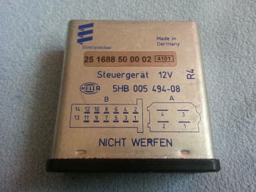
The Airtronic D5 uses the same body but as in the D2 the ECU is internal and it has a combined sensor.
Thus these pictures cover all three models Airtronic D5, D5LC and D5L.
If anyone is servicing a D5 please send us high quality pictures covering the earlier stages for completeness.
Read the notice at the bottom of this page before starting any work.
Click on images for a better quality picture.
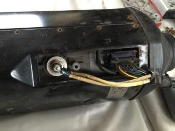
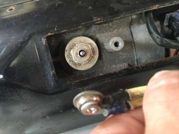
Remove the glowpin wiring nut, its connector is a single part. Tip:- fit the nut back onto the glowpin so it does not get lost.
Bottom plate can be removed on these models.
Unscrew loom cover fixing bolt with a hex key.
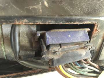
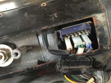
The two retaining latches have to be levered outwards to disengage before unplugging the loom connector.
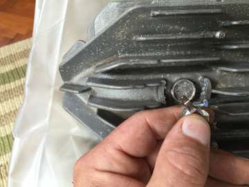
One retaining post has previously been broken. This is not good as when re-assembled the overheat sensor must make good reliable thermal contact.
The sensor is a serious safety feature.
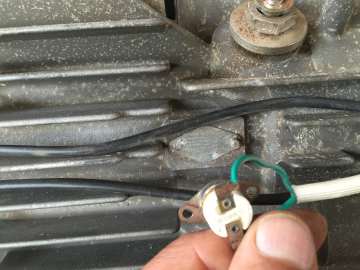
If needed the flame sensor retaining clip is easier to remove, lever with a screwdriver.
Unplug the overheat sensor connector.
The flame sensor removed.
Undo the fixing screws and remove the hood.
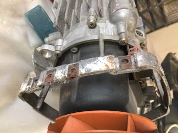
Remove the bolts holding the shield frame.
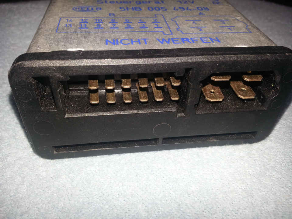
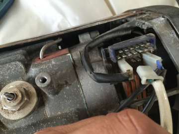
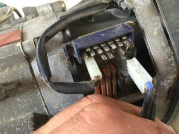
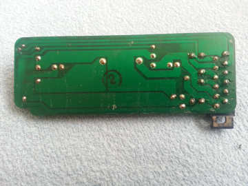
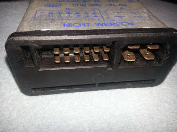
The pin connections, right, look perfect but testing with a meter from the pin to the track, with just a little movement they go open circuit. When desoldered on the backside of the PCB the new solder would not stick to them without thorough cleaning.
Remove the heat exchanger bolts.
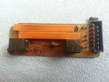
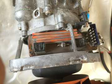
Circuit board removed for repair, leave in situ if not required.
The circuit board can fail due to bad soldered joints to the 12 pin connector. One tested only took some 5 - 10 unplugs for the connections of the pins on the PCB plug to fail.
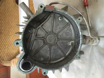
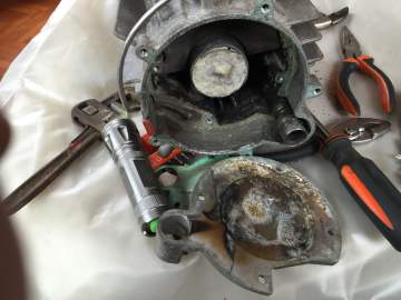
Plate bolts can be very tight, use a good quality screwdriver. Tip:- When reassembling use Copaslip on the bolts to make them easier to remove next time. One bolt has been replaced.
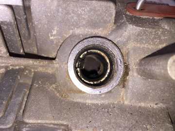
Pull out the glowpin screen by gripping the tab with pliers. Check the end of the fuel feed inlet pipe is clear. There is probably also a ventilation hole like on the D1LCC. The other end is shown on later photos inside the heat exchanger, clean it thoroughly with a piece of wire.
Reassembling the unit.
Reassembling the unit after cleaning is the reverse of the disassembly process with just a couple of points to note.
Always replace the burner gasket even if it looks in good condition.
We know of several instances where a re-used gasket looked good but later failed, leaking fumes into the heated air supply. The only time we would consider re-using the gasket is if the heater is stripped down a second time within a week or so.
Some users recommend using Copaslip on bolts to help future servicing, especially for the heat exchanger plate. We would follow this advice ourselves.
Checking the Fuel Metering Pump Filter
The Fuel Metering Pump contains a fuel filter which should be checked and cleaned as part of the service. Details are on the D2 service page
Airtronic D5 case and ECU is different so early disassembly differs slightly from the D5LC. This should be straightforward, specific instructions are not given here but good quality photos would be welcomed for inclusion here please.
The D5 Troubleshooting & Repair manual has photos. The large bung on the D5 covers the glowpin, the smaller one an air mixture adjuster.
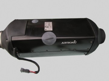
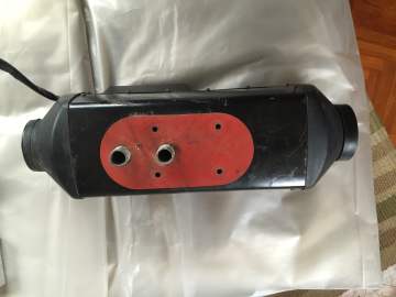
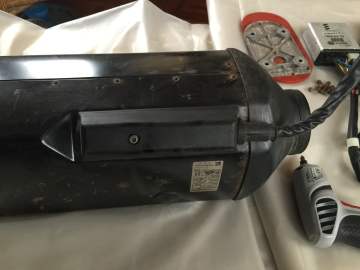
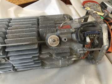
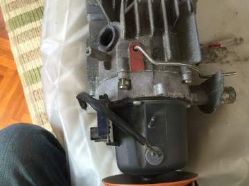
D5LC front with loom entry cover.
Case is held by screws.
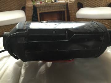
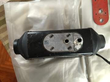
D5LC case rear. The small bung covers the air mixture adjuster.
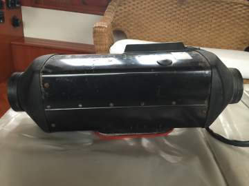
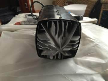
Bottom of the D5LC with its mounting seal.
The fixing studs have been completely removed but they can be left in place if not replacing them.
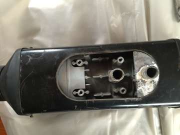
Bottom plate removed.
Possibly not necessary to do so.
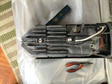
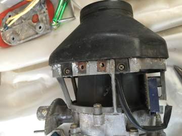
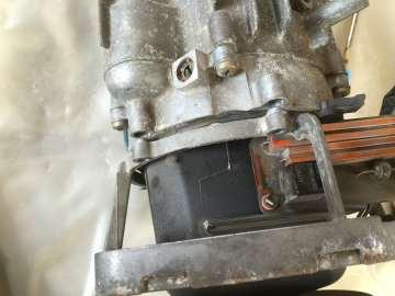
Heated air outlet hood screws are visible.
Undo fixing screws and remove heating air outlet hood. Remove case fixing screws.
The connector side retaining lugs are visible. Remove the loom.
It may not be necessary to remove the heat plate but if required lever up the heat plate retaining clips with small screwdriver(s) or thin nosed pliers and remove the plate. The manuals do not show heat plates for D5LC or D5L models.
Clips are shown more clearly on later photos and often break.
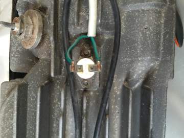
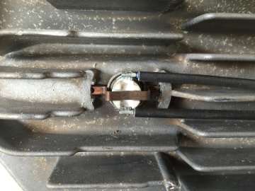
The D5LCC and D5L have 2 separate sensors. The Airtronic D5 uses a single combined sensor fitted in the left hand sensor position.
Only remove the overheat sensor if required as the retaining clips often break.
An alternative clip is a starlock push on fastener.
Unplug the flame sensor connector.
The motor connector can be left plugged in.
It may not be necessary to remove the bottom heat plate. The manuals do not show any plates for D5LC or D5L models, only on the D5 so possibly these were added on later D5LC production runs.
This heater is a 2003 to 2005 model.
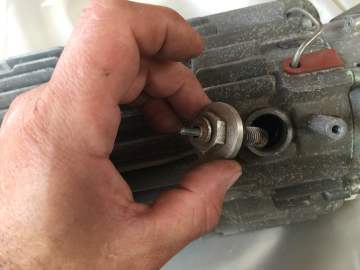
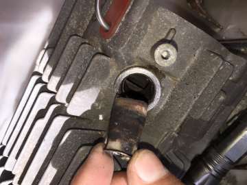
Remove the glowpin, 19 mm spanner. Inspect and clean. It can burn away close to the tip. Also the wire may sag and short circuit to the next turn. The seal has a soft mastic type material, treat carefully.
D5 / D5LC / D5L / D1LCC...... have old type glowpins unlike the D2 / D4 which have the later ceramic glowpins. Failure of these older generation glowpin types are fairly common, usually failing open circuit.
Replacements are available.
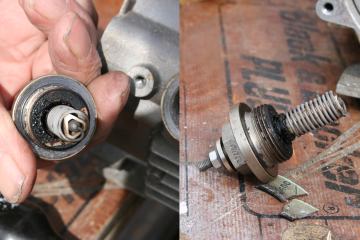
If the old screen is in good condition clean and retain as an emergency spare, dump ones like this! Fit a new screen during reassembly.
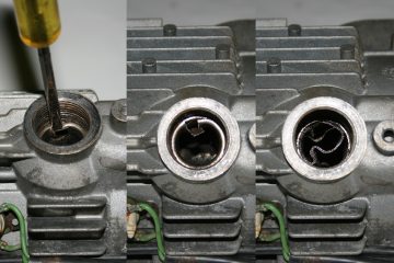
If the screen cannot be removed with pliers.
1 Bend the tab out of the way then drive a
screwdriver behind.
2 The ring nearly broken, lever inwards to break it.
3 Prise the screen away from the sides until loose.
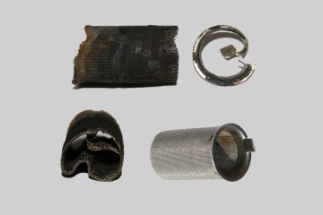
A clogged D1LCC Glowpin screen.
Much of the surface carbon broke away whilst removing. We were very surprised it had kept going for so long, a D2 would have stopped long before this, the larger screen must help. New screen lower right.
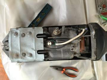
View of the circuit board in situ.
Above is the fuel / air mixture control.
Leave this alone unless you have an exhaust analyser to adjust for the best burn.
The circuit board slides out if needed.
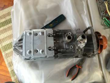
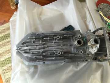
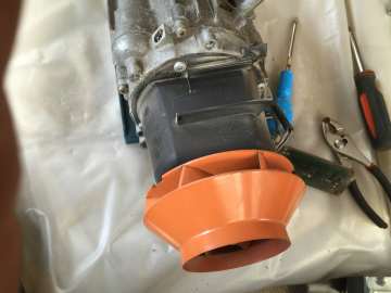
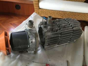
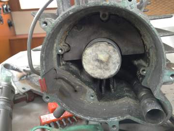
Separate the heat exchanger and blower units. The location of the O ring is not shown precisely in the manual or in these photos so check its position.
The heat exchanger semi circular plate and burner are not removable so chemical or industrial ultrasound cleaning may be required. Follow all chemical safety instructions. There is a small hole beside the fuel pipe entry which I suspect is a ventilation hole to the glowpin screen. Clean it thoroughly with a piece of wire. The white central blob is the old felt washer.
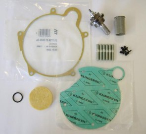
Service kits or individual parts are available from dealers or Ebay. Some kits include a fuel filter, usually not needed. M6 Studs and repair rivets are optional. The O ring is not shown in the photos, check fitting position when disassembling. The D5 manual does not show an O ring fitted. The plate gasket must always be replaced. Keep the old glowpin as a spare or replace it only when it fails. It can be replaced without major dismantling.
Disclaimer
You use any information and advice we give entirely at your own risk.
If you do not accept this do not use this site, go to an Eberspacher dealer.
I have tried to make it as accurate as I can but accept no liability for errors or problems caused by following our pages.
Some of the information is only suitable for people with a good aptitude for mechanical and electrical repairs. Any DIY involves some risk of accidents and you must decide if you are capable and can do it safely before carrying out any work.
You should also ensure your DIY is done to a professional standard in order to avoid creating potential hazards and insurance invalidation. Boat installations must strictly comply with Marine regulations.